This website is now archived. To find out what BERG did next, go to www.bergcloud.com.

Blog posts from December 2007

Beautiful Beolit

A couple of months back I visited Tom and Durrell at Luckybite to discuss some of the Olinda development. During our conversation, Durrell described one of his favourite portable radios, the Bang & Olufsen Beolit 600. I bought one.

Beolit radio

The range was produced between 1971 and 1981 and aside from its elegance and good audio quality, the detailing is very deft.

Radio details

Tuning with magnets

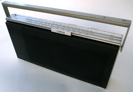
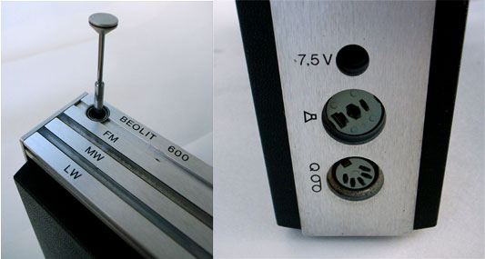
The chassis is constructed from aluminium strips, holding plastic shells front and back. The controls for the radio are spread out along the front and back edges of the top face. On the back edge are buttons for band selection and two sliders for volume and tone. The entire front edge is a horizontal tuning slider.

Tuning slider long
Tuning slider overview

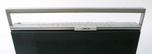
The slider can be grabbed and pushed quickly up and down the length for coarse tuning. To tune precisely the two small kinked wheels are rolled under the thumb to give fine control. The remarkable detail is in how the selected frequency is indicated:

Tuning slider detail

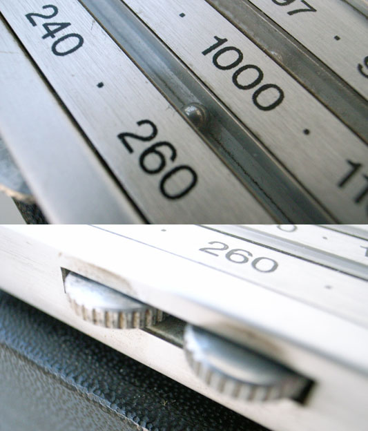
Two very small steel bearings sit in covered grooves in the aluminium chassis, one for each tuning band. The tuning slider conceals a magnet, which drags the bearings along the scale inside their grooves (the aluminium is of course unaffected by the magnetism). The position of the bearings corresponds to markings on the surface of the radio which indicates the frequency the radio is tuned to.

It’s a really nice example of celebrating functionality. There is no functional need for the bearings. The additional cost to develop and manufacture can’t possibly have made financial sense. Why not use an arrow? But tuning is what radios do, and something which articulates this most familiar function so poetically just had to be done.

I love how the furthest bearing twitches along more slowly than the closer one.

Construction

Structurally the radio is a square of four lengths of extruded and cut aluminium, with the front and back plastic shells tucked in. What’s exciting is that taking the radio apart isn’t work: there are no machine screws or self-tappers.

Base fixings
Base fixings 02

The base plate of the radio can slide. Sliding it a little way first unlocks the back shell. Removing the back allows the base to slide more, which releases the more rarely removed front shell. All this is achieved with a clever system of grooves and nooks.

Beolit in bits

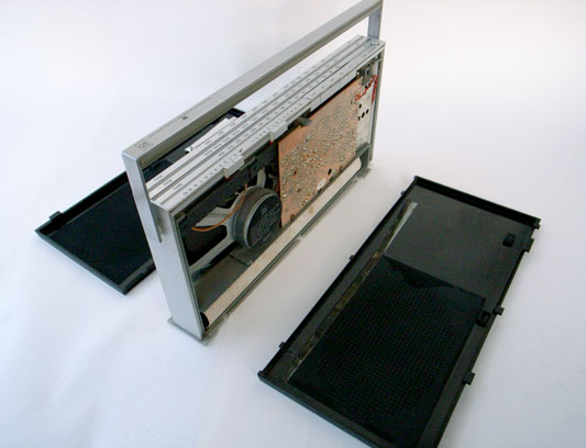
Coming off first, the back shell gives access to the battery. The front shell reveals something else.
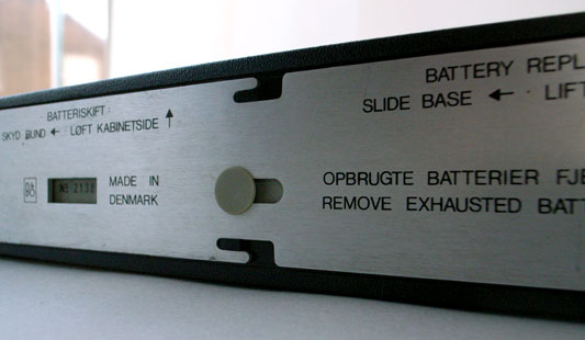
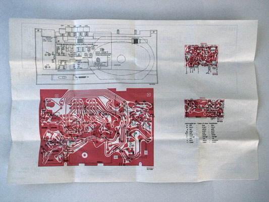
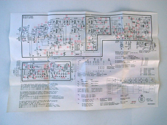
The repair manual

Inside the front shell, there is a little envelope. Inside the envelope there is a piece of folded paper.

Beolit envelope

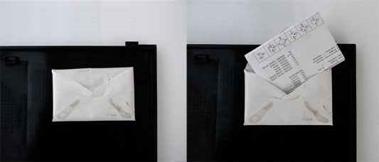
Screen printed on the paper are all the instructions for repairing the radio. There is an abstracted circuit diagram and also an image of the actual PCB. The radio contains its own data sheet, physically!

data sheet physical
data sheet abstract

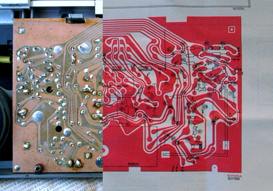
I’ve cut these last two images together to show that the PCB and the print in the diagram are to scale (the screens were probably made from the same drawing).

data sheet and PCB

Olinda connections

One of Olinda‘s jobs is to communicate the potential for hardware APIs. Matt discussed this in detail in his post on widgets.

Olinda is expandable and modular. For this to be effective, the core services of the central unit really have to be accessible from it’s periphery. We don’t mean superficial expansion or extension of lineout (like adding a speaker), but actually change the nature of the object, to grow from it’s core. There is an obvious predecessor in consumer electronics in hi-fi separates, although it is limited in that the turntable cannot affect the services available through the interface, on the amplifier. The extensions for Olinda will be able to make the radio a new object with each addition (In our case main and social do this).

Part of this project is to discuss modularity. (While designing the physical radio itself is a large part of the work, the larger project is about communicating the core ideas.) The connector is effectively a serial connection between the main unit and the extensions (plus a few extras). This could have manifested as a serial cable with two sockets on each unit, much as they appear on old printers and the like. Although traditional connections and cables have historical precedent, they do not sufficiently raise modularity.

We were clear early that the mechanism for connection should be visible, rather than discreet. It should go out of its way to invite extension (Matt discusses these ideas with reference to the Levittown Homes in his talk, The Experience Stack). One should see how it extends and the connection be mechanically explicit. The use of the mechanism, the act of extending should feel really satisfying too. For the reasons described above the serial cable fails.

Connector developments

Each module needs to include a surface which connects to the previous. Software and power aside, the implication should be that the units are infinitely extensible. To begin with we examined the possibility of a mechanical connection, something with toggle clamps or vertical stacking.

Japanese Joinery 01
Japanese Joinery 02

Kiyoshi Seike’s book on Japanese joinery includes some beautiful imagery, above.

wood test

In some early work we experimented with connections in wood. As the process progressed and more influences on the form of the radio emerged, we chose to explore a system of magnets and studs. This delivered the most satisfying feeling and the building brick aesthetic taps nicely into the familiar heritage of Lego.

This idea came out of both Apple’s MagSafe power connector, and a previous project on RFID which touched on using magnets for tactile feedback to make reading RFIDs more like pressing a button

So in the final model, the entire end surfaces of the modules are positive and negative connectors.

Milled 01
Milled 02

These two images show the progression of the studs, looking for a good fit and a good feel. These models also explore how the magnets are to be included.

copper-connector.jpg

There are eight electrical connections between the modules. These are a line of sprung copper domes, held against copper blanks on the opposite face by the force of the magnets.

Most recent test

Above is the most recent and final connectors prototype before machining, and the image following gives an impression of the final form.

CAD connectors

Much of the early work in this process was produced with the help of Jeff Easter, thanks Jeff!

Olinda interface drawings

Last week, Tristan Ferne who leads the R&D team in BBC Audio & Music Interactive gave a talk at Radio at the Edge (written up in Radio Today). As a part of his talk he discussed progress on Olinda.

Most of the design and conceptual work for the radio is finished now. We are dealing with the remaining technicalities of bringing the radio into the world. To aid Tristan’s presentation we drew up some slides outlining how we expect the core functionality to work when the radio manifests.

Social module

Social Module sequence

This animated sequence shows how the social module is expected to work. The radio begins tuned to BBC Radio 2. A light corresponding to Matt’s radio lights up on the social module. When the lit button is pressed, the top screen reveals Matt is listening to Radio 6 Music, which is selected and the radio retunes to that station.

Tuning

Tuning drawing

This detail shows how the list management will work. The radio has a dual rotary dial for tuning between the different DAB stations. The outer dial cycles through the full list of all the stations the radio has successfully scanned for. The inner dial filters the list down and cycles through the top five most listened to stations. We’ll write more on why we’ve made these choices when the radio is finished.

Recent Posts

Popular Tags